

I’m with you on it being fascinating, but this also has the same drawback as the stock camera in my Qidi which is that the frame rate is ass. And mine actually manages as many as 6 or sometimes even 8 frames per second!
I imagine this is in no small part due to the video compression happening in the dinky SoC on the printer’s mainboard, and obviously it prioritizes timing the print head moves over everything else. When my printer is idle and preferably showing a largely black frame (i.e. the internal lighting is turned off) the framerate rockets into the 30’s. I’ve toyed with the idea of splitting the camera out onto a separate board since it’s only USB internally and can be unplugged and the wire rerouted, but thus far I haven’t cared enough to overcome my laziness in setting it up.
To be fair I also have a GoPro that’s usually not doing anything productive. If I really wanted to go whole hog I could adhere one of its little mounts in there somewhere and power it off one of the USB headers. I’m sure there’s enough clearance inside the case for it, and then we could print at 4K60.
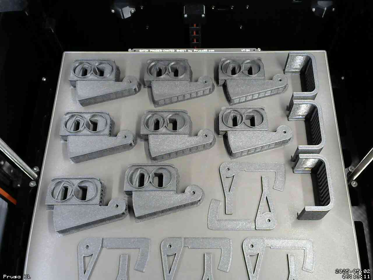
I’m much more interested in whatever mechanical contrivance you’re printing parts for, there.
the frame rate is ass
Well, in my case, I just bolted an el-cheapo supermarket-bought webcam inside the printer’s enclosure. It’s terrible in every way: it has fixed focus and the bed of the printer isn’t in the focus plane, it has terrible rolling shutter and no manual exposure control.
The webcam is connected to one of the production servers nearby that serves up the video as a MJPEG stream using Motion. It’s Motion that limits the framerate to 2 fps, and I configured it that way on purpose: I just need the camera to know whether something terrible has happened to the print and I should stop it remotely - like parts lifting or coming fully unstuck from the sheet, extruder collision… I don’t need quality video for that, so I chose the low framerate and poor resolution primarily to save bandwidth on my home internet, which is kind of crap because I live deep in the forest 🙂
I’m much more interested in whatever mechanical contrivance you’re printing parts for, there.
It’s a bit complicated to explain, but to make it simple: the top parts are optical couplers. They have a slot and a dovetailed circular rail inside that you can’t see because it’s buried in the support. The bottom parts are shutters that ride in the rail and block off more or less of the light in the side of the couplers that has the rail, and have a lever on the other side. The side parts are just mounting clips to hold the couplers onto the optical measurement instruments they’re meant to be mounted on.
Those parts cost cents to make and work just as good as multi-hundred dollar professional optical attenuators, and they’re a lot more convenient for a quick manual adjustment that doesn’t require a precise number of decibels of attenuation.
Finished print 🙂